Shaped wire tolerances should define the allowed variation of specific features under agreed conditions. Start with the dimensions and surfaces that affect fit, then state the limits, references, part condition, and measurement method for each requirement.
Two reports can both say “width acceptable” while referring to different places on a curved section. A useful drawing makes that difference visible before samples or orders are approved. This guide shows how to organize feature limits, separate straightness from cross-section size, and agree what the measurement results mean.
Key takeaways:
- Define each critical feature rather than asking for one precision number.
- Separate size limits from corner geometry, contour, straightness, and twist.
- Agree where, how, and in what condition the wire will be measured.
- Treat instrument resolution, measurement uncertainty, and product tolerance as different concepts.
- Confirm supplier exceptions against the approved drawing and revision.
What shaped wire tolerances need to define
Nominal values and allowed limits
A nominal dimension identifies the intended size. A tolerance states the allowed variation around, or in relation to, that requirement. The drawing needs to communicate both clearly, using consistent units and the chosen drawing conventions.
Begin with a feature identifier and a clear description. Is the requirement the distance between two faces, the overall height, a corner radius, or an angle? Shaped wire tolerances become easier to review when each requirement refers to something the buyer and supplier can both identify.
For shaped wire tolerances, distinguish product size from allowed variation. A supplier’s listed material or size range does not establish the tolerance for a particular drawing. Ask for confirmation of the requested feature, material, size, and delivery condition.
Size, contour, and orientation are separate questions
When defining shaped wire tolerances, matching width and height does not fully define a curved or grooved profile. Describe the contour and local features that matter to the assembly. If an angle or the direction of a face is important, include the relevant requirement instead of assuming it follows from the outer dimensions.
The term “profile wire” describes a product. It is not automatically the same as a formal geometric profile tolerance on an engineering drawing. Use the selected drawing standard and engineering review for formal geometric controls; this guide does not replace those rules.
Review the shaped wire selection overview if you are still choosing the section. The overview covers geometry and application inputs; this article focuses on making the feature requirements measurable.
Critical features and general requirements
Identify the faces and dimensions that affect location, clearance, contact, or later operations. Give those features clear attention. Keep the remaining requirements defined too, whether through individual limits or an agreed general specification.
Shaped wire tolerances should reflect the component’s needs, not simply repeat the tightest number found in a catalog. Separate approved buyer requirements from values the supplier is being asked to propose. Review the proposed change before adding it to the order.
Specify width, thickness, radii, and functional references
Mark the feature that performs the function
Show the reference surfaces used to locate the wire or assess its geometry. State which width, height, or thickness is relevant and where the measurement applies. For a section with a groove or several flat faces, a single overall dimension can leave important details undefined.
Link shaped wire tolerances to feature identifiers such as W1, T1, or R1 in the drawing and requirement table. These are convenient editorial examples, not prescribed symbols for every drawing standard. Keep the actual identifiers consistent with your controlled documents.
For oval profile wire, distinguish the major and minor dimensions from the complete contour. Confirm what needs to be controlled for the mating part. Do not infer contact pressure, strength, or assembly suitability from the section name alone.
Define corners, transitions, and local contours
Corner geometry can matter even when the overall dimensions are unchanged. Show whether a radius, curved transition, groove, or edge form needs a specific definition. Avoid treating “sharp,” “rounded,” or “precision” as complete acceptance instructions.
Shaped wire tolerances for one dimension do not automatically resolve every adjacent feature. Check how the corner connects to the functional faces and how that relationship will be assessed. Where formal geometric controls are needed, have the drawing reviewed using its stated standard and edition.
Read a simple size-limit example
Illustrative scenario: A design engineer named Casey uses a hypothetical width of 5.00 ±0.05 mm to explain a drawing requirement. The arithmetic lower limit is 4.95 mm and the upper limit is 5.05 mm. Casey records the feature, units, and measurement basis with those limits. These invented teaching values are not Jingzhou Metal’s capability, a recommended tolerance, or proof of supplier acceptance.
This example concerns a simple size limit. It does not describe every type of geometric tolerance or establish a measurement decision rule. A result near a limit needs care. Use the agreed method and decision rule to assess it.
When reviewing shaped wire tolerances, keep the intended feature and its permitted variation together. Do not copy the numerical limits into another material, profile, or size without design review. Supplier feasibility must be confirmed for the actual specification.
Separate straightness, twist, and cut length
State the evaluation length and part condition
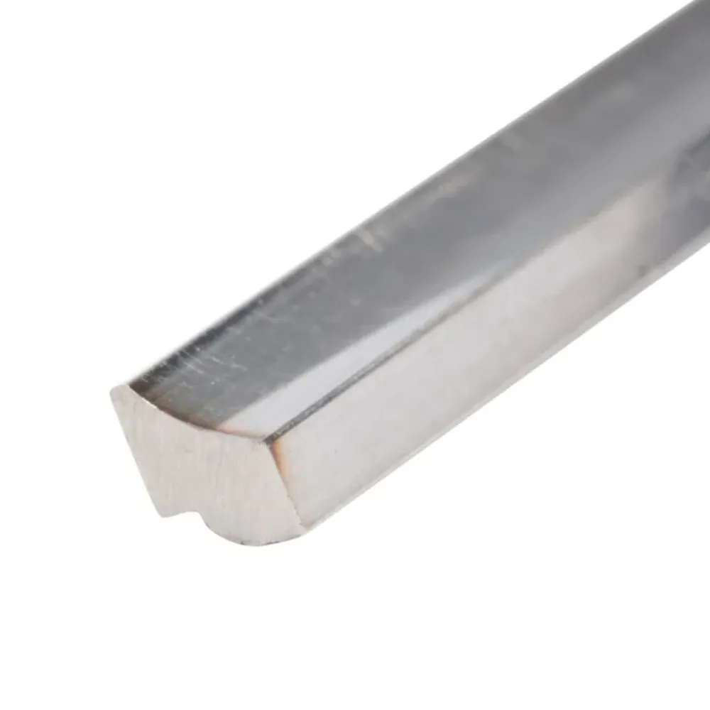
Cross-section limits cover only part of shaped wire tolerances. If straightness matters, state the feature being evaluated, the length involved, and the measurement conditions. Confirm whether the assessment concerns the delivered form or a defined condition after an agreed operation.
Describe the support or free-state arrangement where it affects the assessment. The buyer and supplier should not be left using different setups without knowing it. Shaped wire tolerances for straightness need more context than the statement “wire must be straight.”
Do not invent a universal allowable deviation per metre from a general product description. Use the requirement established for the component, and ask the supplier to review its feasibility and method. The same care applies when specifying a cut length or an end condition.
Define orientation and twist separately
Shaped wire tolerances may also need to control orientation along the delivered length. Describe what faces or features define that orientation, over what length it is assessed, and how it will be measured. Do not treat a width reading as evidence that twist requirements have also been met.
Shaped wire tolerances can therefore involve several different checks on the same piece. Identify them individually so that the report addresses the drawing rather than only the easiest dimensions to measure. Keep units and evaluation lengths visible in the requirement record.
Revisit requirements when the delivery form changes
Coils, straightened lengths, and cut lengths describe different supply tasks. State the form you require and the operations included in the quote. A change in delivery form is a reason to review the applicable requirements and measurement conditions, not a reason to assume the same checks apply unchanged.
NAN CHENG’s shaped wire specification guide identifies critical dimensions, straightness, twist, and measurement methods as items to define. It is a supplier’s engineering guide, not a universal tolerance table or a statement of Jingzhou Metal’s production limits.
For the broader product discussion, use the custom stainless steel profile wire range as a starting point. The order still needs its own accepted material, geometry, condition, and supply requirements.
Agree how shaped wire tolerances will be measured
Compare the measurement task before comparing numbers
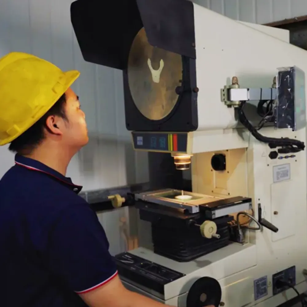
Define the feature and reference used by the measurement method. Record the part position, preparation, support, and sampling location where they affect the result. Choose a method that suits the shape and the task.
Agree the instrument or assessment method with the people responsible for the inspection. Do not choose a tool just by its decimal places. Access to the feature, contact or optical setup, and the defined contour all need consideration.
Illustrative scenario: A quality engineer named Jordan compares two reports with matching width and height values for a hypothetical rounded section. One report measures across the outer envelope; the other also assesses the corner contour required by the drawing. Jordan first checks the feature definitions and methods before drawing a conclusion about compliance. This is an invented example of measurement alignment, not an actual dispute or rejected shipment.
Distinguish resolution from uncertainty
The BIPM vocabulary entry for resolution relates it to an input change that produces a perceptible change in the indication. Resolution is not a complete description of how well a measurement task has been performed.
Shaped wire tolerances state the product limits. A reading comes from a measurement process. More displayed digits do not, on their own, prove that the process can support the required acceptance decision. Review the measurement system in the context of the feature and limits.
The BIPM entry for measurement uncertainty concerns the dispersion of values attributed to the measured quantity, based on the available information. Keep uncertainty separate from the allowed variation specified for the product. This article does not provide an uncertainty budget or a fixed instrument-to-tolerance ratio.
Record the shared measurement basis
Use a short alignment record for shaped wire tolerances. Confirm that both parties assess the same task. Keep it with the drawing revision and inspection requirements. The record need not duplicate a complete laboratory procedure, but it should identify where that procedure or method is defined.
| Measurement item | What the buyer and supplier should agree |
|---|---|
| Feature and reference | The exact size, surface, corner, contour, or orientation being assessed |
| Part condition | Delivery form, relevant preparation, and defined support or free state |
| Location and length | Where the assessment applies and any stated evaluation length |
| Method and setup | The agreed measurement approach and its relevant settings or references |
| Reporting | Units, feature identifiers, drawing revision, and required results |
| Acceptance basis | How results will be assessed, including cases near a specified limit |
Shaped wire tolerances are easier to discuss when the measurement record answers these questions. If two results differ, first review whether the parties used the same feature, method, state, and reference. Do not settle the difference by choosing the report with more decimal places.
Confirm feasibility and document exceptions
Review the complete product specification
Review shaped wire tolerances alongside the material grade, condition, profile size, later operations, and delivery form. Ask the supplier to confirm what it accepts and to identify exceptions. A general precision claim is not confirmation of a particular drawing.
Do not assume that published shaped wire tolerances for another company or product apply to your order. Keep supplier-specific capability examples separate from the buyer’s requirements. Confirm the actual material, geometry, size, process scope, and measurement basis in the quotation review.
The drawing and RFQ checklist covers the full inquiry package. Use this article’s feature record within that package rather than creating two conflicting sets of dimensions or instructions.
Use a feature-by-feature requirement record
The following template organizes the review. Fill it from the approved drawing and project requirements; it is not a Jingzhou Metal standard tolerance chart. Use a separate row for each critical feature so that a proposed exception remains visible.
| Field | Entry to record |
|---|---|
| Feature identifier and function | Drawing label and the fit or function it controls |
| Nominal and limits | Required value and allowed variation, using the drawing’s conventions |
| Units and reference | Units, functional face, and orientation or reference definition |
| Evaluation length and state | Applicable length, delivered condition, and support arrangement |
| Measurement basis | Method or controlled procedure reference |
| Supplier response | Accepted requirement, proposed alternative, or unresolved question |
| Control record | Drawing revision and the document approving any change |
Shaped wire tolerances should remain tied to that control record after the inquiry is complete. An accepted quote, a sample approval, and a production-lot inspection have different purposes. Define which approval releases each stage instead of assuming one document covers them all.
Discuss your drawing requirements with Jingzhou Metal using the feature record and the complete RFQ package. Include the requirements that need review; the inquiry does not establish feasibility or a universal precision guarantee.
Recheck the requirement after a change
Illustrative scenario: A buyer named Riley changes a hypothetical inquiry from coils to straightened cut lengths. Riley asks for review of the length requirements, straightness evaluation, profile orientation, and support conditions used in measurement. The revised quote and drawing references are checked together before release. This scenario is invented; it does not claim that a particular process improves straightness or that Jingzhou Metal accepts any stated requirement.
Recheck shaped wire tolerances if the material condition, corner, length, or measurement method changes. Check whether the supplier’s earlier response still applies. Keep unresolved items open until the responsible buyer and supplier functions have addressed them.
Questions about shaped wire tolerances
Is there one standard tolerance for every profile?
Do not apply one unqualified number to every section. The relevant requirements depend on the feature, material, dimensions, delivery condition, and applicable specification. Agree the shaped wire tolerances for the actual drawing and identify the standard or customer requirement where it applies.
Does matching width and height prove the contour is correct?
No. Matching size readings do not confirm every feature covered by shaped wire tolerances. State the contour features required for the component and agree how they will be assessed. Keep those requirements separate from simple size readings.
Can a supplier’s published precision replace drawing limits?
No. A capability statement describes a stated scope and may have conditions. Shaped wire tolerances for your order need supplier confirmation against the actual requirements. Do not transfer a number from another profile or manufacturer into a purchase specification without review.
Do more decimal places mean a better measurement?
The number of displayed digits does not establish the full measurement capability. Review the method, instrument, feature access, part condition, and measurement uncertainty. Agree how the resulting measurements will support the acceptance decision.
What should we check if buyer and supplier results differ?
Start with the drawing revision, feature definition, units, reference, part state, and measurement method. Review the acceptance basis rather than treating either report as automatically decisive. Record any agreed change and its effect on the affected requirement.
Turn the drawing into an agreed specification
Define the critical feature, its allowed variation, and the conditions used to assess it. Keep size, contour, straightness, twist, and cut length distinct. Then ask the supplier to confirm the requirements and record any exceptions against the controlled drawing.
Request a custom profile wire quote with your drawing, material, delivery form, and inspection needs. Use shaped wire tolerances that are agreed for the project, and keep the measurement basis with the accepted specification.